| Electric | |
|---|
| Power Supply | 24 VAC/VDC, -20%/+15%
50/60 Hz,
reverse polarity protected |
|---|
|
| Power Consumption | 5 VA (0.2 A) w/ (1) remote sensor
connected |
|---|
|
| Sensor Performance | |
|---|
|
| Gas detected | Carbon monoxide (CO) |
|---|
|
| Sensor element | Electrochemical, diffusion |
|---|
|
| Range | Span field adjustable
from 0-200 to 0-300 ppm
via calibration,
0-250 ppm factory set |
|---|
|
| Stability & Resolution | ± 3.0 ppm of reading |
|---|
|
| Repeatability | ± 3.0 ppm of reading |
|---|
|
| Long term output drift | < 0.4% signal loss/month |
|---|
|
| Response Time | t90 < 50 sec. |
|---|
|
| Sensor life expectancy | 3-5 years, normal operating
environment |
|---|
|
| Sensor coverage | 5,000 sq. ft., max 10,000 sq. ft.
(465 m2, max 930 m2),
under “ideal conditions” |
|---|
|
| Installation Location | |
|---|
|
| Mounting height | 5 to 6 ft. (1.5-1.8 m) above floor |
|---|
|
| Type of Control | |
|---|
|
| General | Four-stage (S1 to S4) control,
assignable up to two (2) binary/
relay, horn/audible alarm, and
24 VDC / 50 mA switched
outputs, i.e. low-high stage for
relay output, horn / audible alarm
and switched 24 VDC at any
stage for remote alarming |
|---|
|
| Analog input | One (1) 4-20 mA, for additional
remote sensor, load < 55 mA /
200 Ω, reverse polarity protected |
|---|
|
| Analog reading | Current and mean (average)
value |
|---|
|
| Stage level/setpoint | Field adjustable over full range,
four (4) stages (S1 to S4) per
analog input, assignable to
current or mean (average) value |
|---|
|
| - hysteresis/ switching differential | Selectable for each sensor point |
|---|
|
| Digital input | One (1); can be assigned to any
relay (R1, R2). |
|---|
|
| - application | Remote audio/visual alarm reset
or override function |
|---|
|
| Relay outputs (R1, R2) w/ status LEDs | (1) SPDT (R1), and (1) SPST-NC
or SPST-NO (R2),
jumper selectable |
|---|
|
| Contact rating | 30 VAC/VDC, 0.5 A, max. |
|---|
|
| - each stage level (S1-S4) | Assignable to any relay |
|---|
|
| - sensor fail-safe | Assignable to any stage level |
|---|
|
| Time delay switching | Selectable for make and brake of
each sensor point (SP1 to SP2)
0‑9,999 seconds |
|---|
|
| Analog output | One (1),
(0)4‑20 mA, load < 500 Ω;
(0)2-10 VDC, load > 50K Ω;
jumper selectable;
polarity protected,
assignable to low, high or
averaging of sensor inputs |
|---|
|
| VDC switched output | One (1) 24 VDC, 50 mA max |
|---|
|
| Audible alarm | 83 db @ unit, enabled or
disabled, selectable; assignable
to stage level S1, S2, S3 or S4 |
|---|
|
| Alarm acknowledgment | Menu-driven and system reset
function for latched relays |
|---|
|
| User Interface | |
|---|
|
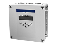
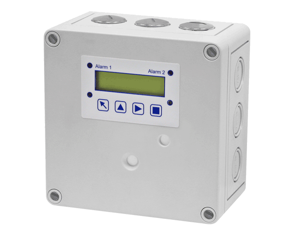
| Keypad type | Refer to illustration “Keypad User
Interface” |
|---|
|
| Touch buttons | Four (4) |
|---|
|
| Status LED’s | Four (4), for system on,
stage status, and failure |
|---|
|
| Digital display | Liquid Crystal Display (LCD),
two lines, 16 characters per line,
1 digit resolution |
|---|
|
| - unit display | Menu selectable, per sensor;
ppm, %v/v, %LEL, °F or % RH |
|---|
|
| Environmental | |
|---|
|
| Permissible ambient | |
|---|
|
| - working temperature | 14°F to 122°F (-10°C to 50°C) |
|---|
|
| - storage temperature | 23°F to 86°F (-5°C to 30°C) |
|---|
|
| - humidity | 15 to 95% RH, non-condensing |
|---|
|
| - working pressure | Atmospheric ± 10% |
|---|
|
| Physical | |
|---|
|
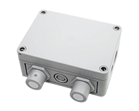
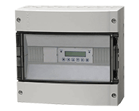
| Enclosure (panel) | |
|---|
|
| - material | Polycarbonate,
UL 94-HB, fire-retardant |
|---|
|
| - conformity | UL 50 standards |
|---|
|
| - color | Light gray |
|---|
|
| - protection | NEMA 4X (IP65) |
|---|
|
| - installation | Wall (surface) mounted,
or single gang electrical box |
|---|
|
| Dimensions (H x W x D) | 5.12 x 5.12 x 2.95 in.
(130 x 130 x 75 mm) |
|---|
|
| Cable entry | 3 holes for 1/2 in. conduit for wall
(surface) mounting and 1 hole on
back side of base plate for single
gang electrical box mounting |
|---|
|
| Wire connection | Terminal blocks,
screw type for lead wire |
|---|
|
| Wire size | Min. 24 AWG (0.25 mm2)
Max 14 AWG (2.5 mm2) |
|---|
|
| Wire distance | Max. loop resistance 450 Ω
(= wire distance plus controller
input resistance) |
|---|
|
| Weight | 0.6 lbs (0.3 kg) |
|---|
|
| Approvals / Listings | |
|---|
|
| - unit rating | NRTL Perf Tested & Certified
Conforms to STD ANSI/UL 2075
City of Los Angeles
CE
VDI 2053, C-No. 418791
EMV-Compliance 2004/108/EWG |
|---|
|
| - relays (R1-R2) | UL Recognized, E41515
CSA, C22.2 No. 0, No. 14
(File No. LR31928) |
|---|
|
| - enclosure | UL Listed, E208470
CSA Certified, E208470 |
|---|
|
| Warranty | Two years material and
workmanship, 12 months normal
exposure for sensor element |
|---|